It has always been the plan that two signal modules should be added to Sæby station, but since there have been many other things that had a higher priority, that task has been put far down the list. However, a day has now been agreed at the main table for Fremo Nordjylland, where we prepare modules for a meeting in February 2027, so I therefore decided to speed up the project with the signal modules. Another reason is that I have been working a bit on three signals in between, and would like to have them ready for the same meeting - and then you have to have a place to put them. The location of the three signals will be one at each end of the main track through Sæby, and one at the branch towards the harbor line. Incidentally, there was no signal at the harbor line's branch at the real Sæby station, but since that branch is occasionally used as a connection to a section out of Sæby, it is practical to have a signal there as well.
In this series on signal modules, I begin by creating the module that connects to the station at its northern end. Once completed, it will feature a section of Aalborgvej, including the level crossing and its barriers; fortunately, there is also room for most of the Annas Foto building.
Anyone familiar with Sæby from the old days will likely remember Annas Foto. It was one of those shops "everyone" knew, as it was centrally located and seemed to have been there "forever."
Module shape
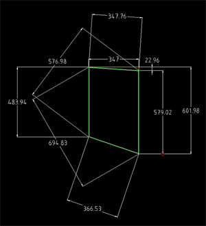
The starting point for any module is a drawing created in QCAD. From this, the dimensions of individual components and the corner angles can be determined.
As the drawings on this page show, not a single corner of the module is a 90-degree angle. This is because the Sæby station modules are 600 mm wide, and the main track is not centered on them. It is also due to the requirement that the signal modules at the end facing away from the station comply with the DK-P15 standard. DK-P15 specifies, among other things, a module width of 500 mm and a centered track alignment; consequently, my signal module ends up with a somewhat unconventional shape.
Module Construction
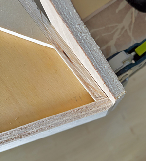
The module is built with a solid base featuring a tongue running along all its edges, while the side panels have a corresponding groove on their inner faces. The side panels overlap the ends of the end plates, concealing the joints between the ends and sides when the module is part of a connected layout.
A major advantage of using a solid base is that the module gains high dimensional stability, ensuring the angles of the finished module match the design drawings. For this specific module, I recess the base so that the distance from the top of the base to the top edge of the trackbed equals the thickness of one sheet of material. For modules featuring more realistic scenery, I recess the base by the thickness of two sheets, allowing for effective elevation changes within the landscape.
I cut the panels using a table saw; the tongue-and-groove joints are also cut on the table saw. Had all the corners been 90 degrees, I would have used tongue-and-groove joints between the sides and ends to guarantee perfectly vertical end plates and a strong connection. However, as none of the corners on this module are 90 degrees, I did not use tongue-and-groove joints at the ends; instead, I had to be meticulous during assembly to ensure the end plates stood vertically. I am considering reinforcing the corners with dowels or by gluing a custom-fitted piece of wood to the inside of each corner.
Assembly is done using glue, followed by brad nails fired from a nail gun to hold everything together while the glue dries.
I prepare the module for leg mounting by fitting a piece of board to a cross-brace, which is installed across the module beneath the baseboard.
- Before installation, I drill holes in the cross-brace for attaching the legs, as well as a larger hole for routing cables.
- I then position the cross-brace without glue and mark its location on the baseboard with pencil lines.
- Next, I drill three holes in the baseboard for the screws used to hold the cross-brace in place while the glue dries.
- I apply a generous bead of glue to the three edges of the cross-brace that meet the baseboard and module sides; I then position and clamp the brace, ensuring it sits perpendicular to the baseboard.
- I drive screws through the pre-drilled holes in the baseboard and into the cross-brace to ensure a tight joint between the two.
- For added reinforcement, I drill two holes through each module side and into the ends of the cross-brace, inserting glued dowels. Before the drill bit hits the cross-brace, I verify that the brace remains perpendicular to the baseboard.
- Once the glue has dried, I remove the screws.
Roadbed plate and baseboard for "Annas Foto"
To create a solid foundation for the track, the signal, and the Annas Foto building, I determine the shape of the roadbed plate. I then cut out the board to form the roadbed; since the baseboard is recessed by only the thickness of a single board, I simply glue custom-cut pieces of board onto the baseboard. The board beneath Aalborgvej also requires thickness adjustments, as I want to give the road a slight slope towards the module's edge—mimicking the actual gradient found at the real-world location. The board beneath the Annas Foto building remains level.
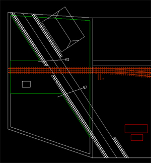
On the drawing of the upcoming module, the roadbed plate is outlined in green. In areas not covered by the roadbed plate, the baseboard will remain visible, sitting one board-thickness lower. These recessed areas will be filled with pieces of extruded foam board to serve as a foundation for the scenery. The landscape here will be modeled as a forest floor, featuring "planted" bushes and small trees. The small, rectangular cutout outlined in white within the roadbed plate marks the spot where the signal shaft will be installed later. Additionally, the drawing includes Aalborgvej—complete with sidewalk sections—as well as crossing gates and the building housing the photo shop.
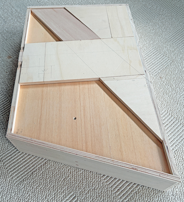
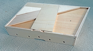
The photo of the raw module shows that the roadbed and base plates for the Aalborgvej section and the Annas Foto building have been cut out. At this stage, they have not yet been glued to the module base, as I still need to rout out ditches extending a short distance inward from the end-plate on the left side of the image.
I have also adjusted the sharp corner at the bottom of the photo so that its width matches perfectly with the station module it will connect to. The tip of the corner has been filed down; as a bonus, this makes the module corner less vulnerable to impacts.
In addition to the ditches, one of the next steps is to cut the opening for the signal shaft. It will be mounted from below at the spot where I have drawn a rectangle containing a "W". I will write about this and much more in future blog posts.